UK Monster Owners Club Forum » .: Technical :. » Mods & How To's » Slow Monster rebuild

Reply
 
Thread Tools Display Modes
Old 20-12-2018, 08:27 PM   #1
Darkness
.
 
Darkness's Avatar
 
Join Date: May 2007
Location: Stockbridge
Bike: M900
Posts: 1,984
Quote:
Originally Posted by 350TSS View Post
there will be clearance, not much but a few mm as the spindle boss which is/will be bearing on the swinging arm clearly protrudes further than the sprocket studs. Chain alignment will obviously be checked on assembly.
Clearance is an absolute, like pregnancy, taxes, rice pudding or death: there is or there isn’t!
__________________
Original and Best since 1993
Darkness is offline   Reply With Quote
Old 20-12-2018, 11:17 PM   #2
utopia
No turn left unstoned
 
utopia's Avatar
 
Join Date: Jun 2010
Location: leicester
Bike: M750
Posts: 4,545
And there they are .. studs and nuts holding the sprocket on, not bolts.
My hub has bolts into threaded holes in the ally hub which are helicoiled as std.
Presumably this is to avoid thread wear in the soft ally hub.
The thing is, I recall contacting dymag to suggest that the helicoil inserts were not really long enough and didn't give enough thread engagement.
At my request they fitted longer ones (or doubled them up, I'm not sure which). There was plenty of room in the hub casting.
The only thing I can't remember for certain is whether this was on the sprocket side or the disc side .. or both.
Anyway, this was about 18 months ago.
Now that I've seen your wheels and, given the timescale needed for a design modification to filter through to production, I'm beginning to suspect that they may have changed to studs following my discussions with them.

Of course this is all conjecture .. I may be entirely wrong.
But it has aroused my curiosity.
I might give them a bell.
Maybe I'm due some royalties .
utopia is offline   Reply With Quote
Old 21-12-2018, 08:54 PM   #3
350TSS
Too much time on my hands member
 
350TSS's Avatar
 
Join Date: Jan 2013
Location: Shipbourne
Bike: M900
Posts: 1,419
Today started well then just went a bit South.
I got the second layer on the tank recess pattern and the fourth and last layer of fibreglass on the air scoop moulds.
I tried Utopia’s shredding the glass matt before laying it out and I should have listened more closely to him a long time ago. It was miles better than cutting into strips, much faster to prepare , much faster to wet down and a better and more consistent finish with the added bonus because it was so much faster to lay down I did not lose the last 10 – 20% of the resin because it went into jelly. Doh!!!!
I then spent an hour or so rubbing down the repaired mould for the Ignitech enclosure and getting it to a smooth and polished surface. I can only take an hour or so of this every day a) because it is boring and hard work and b) because I am losing top layers of skin from my fingertips again and they are becoming painful.
Then I worked on my fuel filler neck. I have to open the bore out from 43 to 45 mm about 11mm below the top of the filler neck in order to provide a positive step for the locking latch to bite. I cannot bore from the other end as that will be closed with a bridge to retain the filter in position so I ground up an old boring tool to give a 90 degree angle on the reverse side of the cutter. The depth of the step is vital to ensure the cap latches so that it sits firmly on the rubber seal and therefore seals the fuel in the tank and also allows the cap itself to sit flush with the outer ring.
It then occurred to me that the latch is steel and the neck and therefore the step on which the latch locates is aluminium.
post images
In the long run the aluminium would wear and the cap would not close. I spent a good hour pondering the solution and finally came up with machining an internal circlip groove and fitting a carbon steel circlip. I have now ordered 2 from Simply Bearings. I need to know the thickness of the circlip to get the right distance from the top of the filler neck so work has stopped on the neck until the circlip arrives. This solution will also involve filing away the inner edge of the circlip groove where the latch engages, this will not be easy but I think a Dremel with a rotary file should make reasonably short work of it.
Finally I spent an hour polishing the filler cap and ring to a reasonable finish.

Unfortunately, I came back an hour later to inspect my handiwork and the aluminium was already oxidising and had changed from a polished aluminium colour to a titanium colour. I will re-polish it and then buff it up and I will then have to clear lacquer it immediately, remembering to mask the key position.
When I got back indoors the postie had delivered my SS mesh which looks to be the right granularity to work but it is incredibly stiff considering the gauge of wire used. My original (probably hopelessly optimistic) plan to cut a large circle then punch a cup shape into the middle of it is quite clearly not going to work.
I think I will have to cut a 40 to 42mm circle for the bottom then a strip about 40mm wide to go round the circumference of the circle. If it was brass it would be easy as I would simply solder or braze the circle and the circumferential column together but with stainless I have no means of attaching the two bits together apart from epoxy resin and that may not last in a petrol (with x% ethanol) environment. I do not want to give up in the idea of an additional filter. Both brain cells are working overtime on this one, wackiest solution so far is to cut the circle about 5mm wider than needed and un thread about a dozen strands form the circumference then knit them into the columnar bit – a definite non-starter.
350TSS is offline   Reply With Quote
Old 22-12-2018, 02:17 AM   #4
utopia
No turn left unstoned
 
utopia's Avatar
 
Join Date: Jun 2010
Location: leicester
Bike: M750
Posts: 4,545
Glad to be of assistance.
I had forgotten about the added bonus of being able to use up all of a mix of resin but yes, that too.
In fact when you actually do the job, it just makes loads more sense if its based on resin quantity, not matting, doesn't it ?
Its all coming back to me now.

On the fuel cap .. which looks great by the way .. I'm guessing that there is a fair amount of zinc in the alloy, to enable it to flow freely when its diecast.
That might be why it oxidises so quickly.
utopia is offline   Reply With Quote
Old 23-12-2018, 04:45 PM   #5
Raven
Guest
 
Posts: n/a
You could stitch the two parts together with stainless locking wire (by hand, of course). If it went far enough into the tank, you could graduate it to see content in litres/gallons at a glance.
Tom
  Reply With Quote
Old 23-12-2018, 09:01 PM   #6
350TSS
Too much time on my hands member
 
350TSS's Avatar
 
Join Date: Jan 2013
Location: Shipbourne
Bike: M900
Posts: 1,419
Raven thanks, better than any incipient plan I have just now, the graduation idea is a good one but I only have 60mm clearance below the filler to the air intake cut out so not really a starter, also my design of filler neck is a cup with the bottom 30mm cut away on both sides of a central " 8 to 10mm bridge" that will stop the filter dropping into the tank
350TSS is offline   Reply With Quote
Old 07-01-2019, 09:16 PM   #7
350TSS
Too much time on my hands member
 
350TSS's Avatar
 
Join Date: Jan 2013
Location: Shipbourne
Bike: M900
Posts: 1,419
This was my first day back in the garage after the “festivities” and a week in a ski resort. I used to love skiing, nearest thing to riding a motorcycle, but alas the arthritis has put paid to that, so I spent a week reading and plotting next steps while my kids enjoyed themselves.
After almost 3 weeks away from the garage it took some time to remember what I had last been doing and where I had got to with each component of the build.
First job tackled was to trim the excess glass fibre from the air scoop moulds and drill through the two halves so that they will align when they are put back together ready for the epoxy compatible gel coat and the carbon fibre cloth. I then split the moulds with mixed results; of the 8 halves 3 came out near perfect, 3 with minor damage/defects and 2 with damage that will not rub out but will need to be filled. This will add at least 3 hours to my ETTC.
The problem once again was the gel coat creeping between the pattern and the polypropylene base plate causing the pattern to be trapped in the mould. The gel goat is incredibly viscous when just mixed with the consistency of treacle and despite waxing the junction between the pattern and the polypropylene base plate it still manages to inveigle itself in between the two components. I will have to get better at this as the tank will be a very large mould and any mechanical locking due to this will be very difficult to resolve.


A bit disheartened I decided to modify my rear tank mounting to make it lighter, neater and probably a bit safer in an accident (previously it had been a fabricated hook to retain a bungee loop that would have attached to a narrow cotton reel bonded to the rear of the tank). Using the same principle for the bungee retention for rear chain tensioner, I knocked up a clamp from 10mm plate through drilled for 2 of the original hinge mounts on the frame then cross drilled it off centre and broke through with a hacksaw to provide a half moon that would clamp the bungee to the seat retention bridge on the frame. (picture to follow).
350TSS is offline   Reply With Quote
Old 08-01-2019, 09:18 AM   #8
350TSS
Too much time on my hands member
 
350TSS's Avatar
 
Join Date: Jan 2013
Location: Shipbourne
Bike: M900
Posts: 1,419
forensic anthropology wages
The clamp is retained by aluminium button head socket screws for a Yamaha fairing - nice and light
350TSS is offline   Reply With Quote
Old 09-01-2019, 09:08 AM   #9
Darkness
.
 
Darkness's Avatar
 
Join Date: May 2007
Location: Stockbridge
Bike: M900
Posts: 1,984
Quote:
Originally Posted by 350TSS View Post
forensic anthropology wages
The clamp is retained by aluminium button head socket screws for a Yamaha fairing - nice and light
The wages are better if you can get on the Time Team, Christmas Lecture circuit, like Prof Alice Roberts?
__________________
Original and Best since 1993
Darkness is offline   Reply With Quote
Old 09-01-2019, 04:18 AM   #10
350TSS
Too much time on my hands member
 
350TSS's Avatar
 
Join Date: Jan 2013
Location: Shipbourne
Bike: M900
Posts: 1,419
Looking at the picture above I need to turn down the heads of the socket screws so the outside diameter matches the width of the clamp, stupidly, I didn’t measure the screw head size before cutting the 10mm plate for the clamp.
I spent a couple of hours finalising the belt cover moulds yesterday which are now as good as I can get them. Filling (and finish sanding) internal contours is a lot more difficult, fiddly and time consuming than the external contours on the patterns.
I also finished fibre glassing the tank recess mould (to take the filler cap) which will now need to cure overnight before I remove the pattern from the mould.
Then I machined the internal circlip groove in the fuel tank filler neck. The 46mm OD internal circlips came with large internal “ears” which when fitted inside the filler neck were too big to allow the cap (which has a tapered lead in to the spring mounted rubber seal) to sit down far enough to seal properly or for the latch on the locking pawl to work at all. I ground the ears down as much as possible without turning the circlip plier holes into slots and that did not work, so I then made the circlip groove as deep as I dared whilst still ensuring that the circlip gripped the inside of the groove and that did not do the trick either. I think I will have to buy a 47mm OD internal circlip and deepen the circlip groove further and see if that works.
Reflecting on something Mr Gazza wrote about clip ons and sitting further back on the seat I have reluctantly concluded that I will have to lengthen my seat pattern. The original pattern length was based on the position of the original Monster seat with the hump located where the profile of the original seat changed from rider to pillion position. I will extend the seat pattern “deck” by c 50mm. Fortunately the deck will eventually be covered by foam and ambla so the finish of the extension is not in any way critical. At present I have nothing to sit on to test the right length for me. At least if it is too long it can easily be shortened before I cover it, vice versa is a bit trickier. The potential downsides of a longer seat are the aesthetic of the final design and possibly the positioning of the rear seat latch. This is the task for today
350TSS is offline   Reply With Quote
Old 11-01-2019, 11:35 PM   #11
350TSS
Too much time on my hands member
 
350TSS's Avatar
 
Join Date: Jan 2013
Location: Shipbourne
Bike: M900
Posts: 1,419
Food poisoning stopped any progress over the last few days, today however I did manage to fit the circlip to the tank filler neck,

check that the filler cap lock located on the circlip and the key could be removed.

Finally I cut the base of the filler neck to allow the petrol into the tank leaving a “bridge” to retain the in-tank filter. The bridge ended up about half the width I had anticipated due to my complete inability to cut a straight line with a hacksaw, fortunately I can file a reasonably straight line.
host pictures online free
I also ordered some fine brass mesh to make the filter which I should be able to solder into a cup shape to sit on top of the bridge
350TSS is offline   Reply With Quote
Old 14-01-2019, 07:06 PM   #12
350TSS
Too much time on my hands member
 
350TSS's Avatar
 
Join Date: Jan 2013
Location: Shipbourne
Bike: M900
Posts: 1,419
The fine brass mesh arrived today and was duly cut and soldered to make the filter - the soldering could have been a bit tidier but overall quite pleased with the result. The circlip retains the filter from above.
350TSS is offline   Reply With Quote
Old 17-01-2019, 03:23 PM   #13
350TSS
Too much time on my hands member
 
350TSS's Avatar
 
Join Date: Jan 2013
Location: Shipbourne
Bike: M900
Posts: 1,419
I knocked this up yesterday out of 6mm aluminium plate to support the CF instrument surround and to provide a top mounting point for the fly-screen. This will be attached to the underside of the top yoke via the current instrument mounting bolt holes.
The rear view CCTV screen and the speedo/rev counter will sit in a CF surround which will be packed with foam rubber. I intend to provide a perspex or ABS lens/cover which will hold them in and provide weather protection for them. The lens will be held down by 7 x 5mm ss button head socket cap screws which will screw into tapped holes in the 6mm plate. There will be a rubber gasket between the lens and the CF surround.
I will bond in a CF diaphragm into the fly-screen (a dashboard) that will stiffen the structure and pick up on the 3 “ears” at the top. I suspect that I will need some struts between the current instrument mounting bolt holes on the top of the top yoke to the two outer “ears” to triangulate the mounting.


Today, using the last of my 6mm plate, I made the inner tank circular plate which is effectively 5 captive nuts and will be bonded into the inside of the tank top to secure the filler cap and the filler neck to the CF recess (also bonded to inside of the tank top).
350TSS is offline   Reply With Quote
Old 23-01-2019, 03:28 PM   #14
350TSS
Too much time on my hands member
 
350TSS's Avatar
 
Join Date: Jan 2013
Location: Shipbourne
Bike: M900
Posts: 1,419
Productive day yesterday, I managed to cut, bend and drill some 3mm clear acrylic sheet to form the lens for the instrument surround. The material is a swine to cut, the recommended way is to score one side with a Stanley knife then place over a block and crack it, but a) this does not really work for curved surfaces unless you have an exact facsimile of the shape you want to cut and b) it does not stop it cracking in whatever direction it feels like cracking. I tried my jigsaw with the finest of blades and managed to shatter two patterns, a fine toothed hacksaw was also tried which was very laborious and also cracked. The Dremel with a 40mm diamond disc got the job done finally, finished with a fine file.
Bending the acrylic sheet was accomplished with the aid of a vice, two blocks of wood and 15 seconds with a hot air gun. Drilling required a new sharp 6mm drill and very light pressure and even then I managed one 1mm crack when the sheet rode up the drill as I broke through (fortunately small enough to be within the radius of the button head screw). In the picture the protective film that the material is supplied with is still attached.
upload images for free

Next I turned my attention to the tank mould dividers, a job I have been avoiding as a) I was not sure how best to do it and b) I knew it would be difficult.
The tank pattern is heavy (maybe 15kg) but the top surface is actually quite delicate as the body filler thickness over the foam in some places is less than a millimetre. I will therefore make the dividers for the top surface first to protect that thin skin. The tank will have to be made principally as a top surface and a bottom surface and then bonded together, however, at the front near the ignition switch and at the rear near the seat bridge the shape of the pattern would mean that the pattern would not release from the mould so additional dividers are required.
As far as possible I want to limit the extent that the inevitable “flash” lines ruin the aesthetic of the finished product and over the past months I have mentally changed the proposed position of the dividers about 6 times. Yesterday, I decided that prevarication had to stop and for better or worse their position had to be fixed.
I am hoping that the tank underside can be made in one piece (not yet proven) and I want to ensure that where the tank top meets the tank bottom that I have a slightly conical junction line about 6 to 10mm deep so that a good bonding surface between top and bottom is facilitated. To best achieve this and not end up with a very messy junction line I think I need the bottom edge of the tank top to be extended downward with a slight opening taper, thus the tank bottom mould will have a similarly conical mating surface to the top mould. (I hope this makes sense).
Here are today's efforts
350TSS is offline   Reply With Quote
Old 28-01-2019, 06:51 PM   #15
350TSS
Too much time on my hands member
 
350TSS's Avatar
 
Join Date: Jan 2013
Location: Shipbourne
Bike: M900
Posts: 1,419
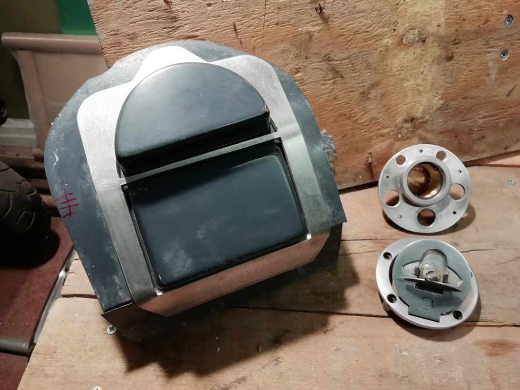
Made these up today, which are to be bonded into the inside of the headlamp shell, basically fancy captive nuts.
Annoyingly, I discovered that the two places inside the headlamp shell where they are due to be bonded are not parallel (by about 4mm). It was then that I remembered when I was making the pattern I just filed the foam by eye fully intending to square them up later and then got distracted and forgot all about it. The mould is in final form and cannot be modified now so I will have to make a jig to hold them parallel inside the shell and fill the correctional void with resin and CF. (2 bits of 8mm studding joined by a hexagon bar internally threaded and 4 lock nuts).
I think I can massage the mistake on the outside of the shell with two appropriately filed alloy spacers.

The tank mould dividers are now all made up. The skirts I made in 1mm polypropylene. At first, I tried to make the skirts in one piece but the number of angles and curves made filing them to shape a nightmare and I resorted to cutting it into sections, each section containing only one curve or one change of angle. The main dividers are in 3mm polypropylene.
I have decided to not bother with the fuel level warning light sensor in the tank because:
a) space to fit the boss under the tank is constrained and the only available place is very close to the rear cylinder head/cam-box;
b) the standard sensor will need a large diameter boss and that would mean buying large hexagon alloy bar and about £50 for a large tap and die;
c) I have a right angle fuel tap with a reserve position anyway.
I am now pondering ways to include a transparent vertical line into the moulding of the tank top surface that will give me a visual indication of the level of fuel in the tank (as per the 1972 Paul Smart Imola 750SS). This solution really appeals, it is simple and elegant, reduced weight, no maintenance and no failure modes.
Current thinking is to lay down the first gel coat and then put an 8mm bore clear plastic tube (open at both ends) vertically in before the second gel coat is applied and then encapsulate it with the carbon fibre cloth.
Problems I foresee are a) retaining the tube in a vertical position whilst the second gel coat is applied, b) getting the carbon fibre to have a straight edge either side of the tube - a blurry line would look awful although if the tank is painted a straight line could be masked into the exterior paint, c) preventing any excess epoxy contaminating the inside of the tube during the laying up of c 6 layers of CF and d) I will need to treat the tank with ethanol resistant resin after the top and bottom surfaces are bonded together and how can I stop the resin getting into or worse clogging up either the top or bottom of the tube? As I write this I think I have a partial solution to the above – bond in a big loop of tube that is accessible from the filler hole and when tank is finished, top and bottom halves bonded together and ethanol resistant resin has been sloshed around simply cut the tube through the filler neck and tuck the now open top end of the tube around the filler neck and push the open bottom end to the bottom of the tank.
350TSS is offline   Reply With Quote
Reply


Posting Rules
You may not post new threads
You may not post replies
You may not post attachments
You may not edit your posts

BB code is On
Smilies are On
[IMG] code is On
HTML code is Off

Forum Jump


All times are GMT. The time now is 03:36 PM.

vBulletin Skins by vBmode.com. Powered by vBulletin® Version 3.8.3
Copyright ©2000 - 2024, Jelsoft Enterprises Ltd.