After a few days messing about with the wiring, I came to the conclusion that a radical re-work was required. There were a number of reasons for this, first, the AMP connectors I made up earlier were not standing up to connection, disconnection and re-connection, second the space that they took up was not real estate that I had spare, third, the use of the heavier gauge wire on a number of circuits was also space constraining and worse the sub looms were not at all flexible.
I also challenged the logic for the heavier gauge wiring, there are only two really significant loads on the bike, the headlamp and the horn. If I use an LED headlamp bulb that load will be at least halved and the horn is only used intermittently (never in my case) so the heavier gauge wiring is redundant. I have used heavy gauge for the earth and for the main power leads through the fuse to the MU unit, the alternator power leads and the battery to the starter solenoid.
I ordered an ABS electronics box from CPC after puzzling over the smallest but still adequate sized one for the job. It is bolted to the back of the CF instrument surround via a thrust bearing so it can rotate when the handlebars move.
The instrument surround is rubber-mounted so I do not think vibration will be a significant problem. Two domestic strip connectors are each bolted by 3 mm SS mushroom head socket screws to the base of the box which is reinforced on the reverse side by a 3 mm aluminium plate. The lower strip connector is raised by a standoff made from a strip of 10 mm plate with a space cut between the retaining bolt centres to allow the wires exiting the upper strip connector to get to the lower exit points in the box (there are 8 exit points in all).
Modifying the box and getting this far with the wiring took nearly 8 hours, although some of that was cogitating about cutting off the AMP connectors.
I am replacing every wire leaving the connection box with thin wall 1 mm wire (the same size wire that comes out of all the Ducati specified switches). This has had an enormous effect on the size of the bundle that has to go around the headstock - reducing it to about 30% of the previous wiring and it is significantly more flexible.
There are still a number of hours work left to complete this, rewiring all the connections to the MU unit and marrying the remaining wires to the back loom which I will not replace but I feel much more confident a) it can be done and b) it was the right thing to do.

ui


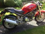


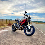
 Roast Beef Monster!


 Linear Mode

