UK Monster Owners Club Forum » .: Technical :. » Mods & How To's » Slow Monster rebuild

Reply
 
Thread Tools Display Modes
Old 30-01-2019, 05:48 AM   #1
350TSS
Too much time on my hands member
 
350TSS's Avatar
 
Join Date: Jan 2013
Location: Shipbourne
Bike: M900
Posts: 1,419
Too bloody cold to stop long in the garage today, I did manage to drill and tap the rear suspension rocker to take a grease nipple. I am not sure what to do with this whether to polish it up or paint it, polishing would look nice but when fitted it is fairly inaccessible so is likely to be looking a bit crusty fairly quickly.

I also continued with filling and rubbing down the elongated seat pattern which with a couple more fillings and rubbing downs should then be complete and ready for the production of the mould divider.
350TSS is offline   Reply With Quote
Old 30-01-2019, 11:06 AM   #2
utopia
No turn left unstoned
 
utopia's Avatar
 
Join Date: Jun 2010
Location: leicester
Bike: M750
Posts: 4,545
On the fuel level indicator ....
How useful is a clear sight line on the tank actually going to be ?
You can only really look at it when the bike is stationary.
On anything other than a short run, this will leave you guessing.
You'll probably end up resetting the trip mileometer and going on mileage since filling up.
I tend to do that anyway, even with a fuel gauge.
In my opinion, the sight tube is more trouble than its worth.
Tbh, I would be more inclined to fit a tap with a reserve on it (space permitting .. which it probably doesn't ?).
Or simply not bother and go by the trip.
utopia is offline   Reply With Quote
Old 30-01-2019, 11:13 AM   #3
mickj
Registered User
 
mickj's Avatar
 
Join Date: Jun 2018
Location: Clevedon
Bike: M1200s
Posts: 560
The other thing I thought is that you have to make sure you cut the bottom of the tube as close to the bottom of the tank as possible, if it curled up at all it would give you a false indication when the fuel dropped below the level of the top of the pipe. Can you reach that far into the tank?
__________________
Keep the rubber side down. Mick
mickj is offline   Reply With Quote
Old 30-01-2019, 06:50 PM   #4
350TSS
Too much time on my hands member
 
350TSS's Avatar
 
Join Date: Jan 2013
Location: Shipbourne
Bike: M900
Posts: 1,419
Good points both Utopia and Mick, I think I will save myself the trouble and use the trip. Thanks

Started today with a bit of rubbing down and filling of the seat pattern and I decided that I would take the opportunity to modify the design a little by raising the leading edge about 25 to 30mm as it interfaces with the tank. This should a) reduce the possibility of gonad/tank contact under heavy braking and b) stop it looking too much like a plank, downsides are it will be more complicated to cut the seat foam and the seat cover will be more difficult to get right.
photo hosting software

Also I had previously tapped out the threads on the instrument panel lugs on the top yoke with the intention of threading in 2 x 65mm studs to retain the instrument panel below and the support bracket for the fly-screen above. I decided that titanium would be best for this threaded stud (130mm threaded). An hour and a half later I had managed a measly 25mm so I gave it up as a bad job and will buy 4 x 30mm titanium socket cap screws and screw them in from top and bottom.
Finally when I was looking for the grease nipple yesterday I came across my 3mm aluminium headlamp support plates which I made ages ago. I was never really satisfied with them as they were heavier than I thought necessary and when I came to lighten them the drill skidded and one of the holes was misaligned. Being on the inside of the bracket, it could barely be seen but I knew it was there and it niggled me. So I knocked up this pattern to make the brackets in CF.
350TSS is offline   Reply With Quote
Old 30-01-2019, 08:22 PM   #5
Darren69
Transmaniacon MOC
 
Darren69's Avatar
 
Join Date: Sep 2013
Location: Sutton In Ashfield
Bike: Multiple Monsters
Posts: 6,025
It would be a neat trick if you could pull it off but as others have said probably of no real use if you have a 2 stage fuel tap. You could always look into the tank and see the actual fuel level.

Didn't Ducati try this on a few of the early 750 Sport or SS bikes using clear fibre glass stripe in the tank and on one of the review bikes there was a dead fly in the clear coat?
__________________
Roast Beef Monster!

Termignoni and Bucci - Italian for pipe and slippers!

S4 Fogarty, S4R 07T, 748, Series 1 Mirage
Darren69 is offline   Reply With Quote
Old 02-02-2019, 07:54 AM   #6
350TSS
Too much time on my hands member
 
350TSS's Avatar
 
Join Date: Jan 2013
Location: Shipbourne
Bike: M900
Posts: 1,419
Spent yesterday with more filling and shaping of the seat pattern, the filler is now over 25mm thick at the leading edge. I spent some time pondering how to cover the seat and concluded that I should use, if at all possible, the inside of the seat hump as a tool box/glove box. This obviously involves more complexity and is only feasible if I can get the top of the seat latch mechanism to be no more than 25mm above the rear frame rails. It also requires that the seat hump foam pad is removable. I love planning jobs like this, working out possibilities, analysing constraints and options and whether or not I have the skill to manufacture what I decide is the best option. I now have a plan but I will not know whether is feasible or worth doing until the seat is made and its precise vertical and fore and aft positioning is determined.
When I got bored with this I looked around for a job that would take an hour or so as the garage is too cold to stay in for any length of time. Some while ago I made up a stay to hold the lower end of the headlight bracket. This was made in steel with brazed in threaded plugs, it is quite heavy and not that well made. I found some lighter gauge steel tube and decided that the attachment could be made from CF so I knocked up a mould to manufacture one in CF.
350TSS is offline   Reply With Quote
Old 05-02-2019, 06:19 PM   #7
350TSS
Too much time on my hands member
 
350TSS's Avatar
 
Join Date: Jan 2013
Location: Shipbourne
Bike: M900
Posts: 1,419
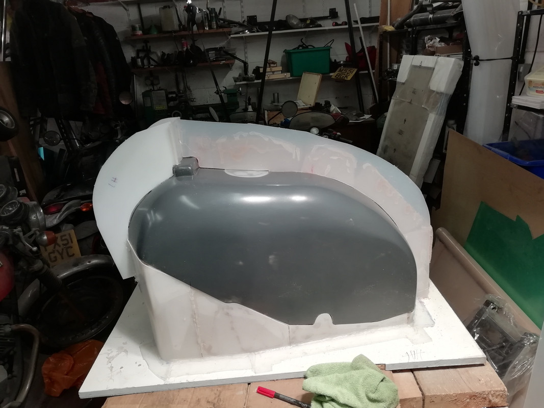
I started the day by fixing the central and front dividers to the tank pattern having first given it 5 coats of release agent, Oasis foam was glued to the right hand side and the dividers bonded to the foam. It went quite well so I thought I had better quit that job before my luck changed.

I then spent some time modifying the seat pattern, removing the nib between the base and the seat hump. I had to use the Dremel on the wood screws holding it on and I needed some filler to repair the inevitable damage This nib was initially necessary to join the two halves of the pattern together but now gets in the way of providing a useful size opening for the tool/glove box to be located in the seat hump. I think I have worked out how to do it now. When the seat is formed it will have an open bottom and I will then continue the base from underneath to the rear end of the hump by bonding in a shaped sheet of CF (formed on a glass plate), this “diaphragm” will form the floor of the glove box.
The near vertical leading edge of the seat hump will have an ambla covered foam pad glued to a CF backing plate. This backing plate will have 2 x tabs that will fit into slots at the junction between the seat base and the hump (forming a crude hinge) and will be secured by a Dzuz fastener at the apex of the hump. The CF backing to this seat pad will effectively be the lid to the glove box.
To provide some form of positive closure to the glove box I cut some 3mm polypropylene to enable a) the hole for the opening to be recessed by 3mm (this will be sealed with a rubber moulding) and b) an indentation to permit the wire captive part of the Dzuz fastener to be flush with the surface of the seat hump. I also started on a mould for the backing plate for the seat hump pad with a 3mm projection that fits into the recess to be moulded into the seat hump itself.
I also started the laborious process of putting 5 coats of release agent on each of the completed moulds.
I am running out of things to make from CF, 2 remaining possibilities are for the rear number plate hanger and the rear LED stop, tail light/indicator holder currently made in aluminium but quite heavy and a little untidy to look at.
350TSS is offline   Reply With Quote
Old 07-02-2019, 04:19 PM   #8
350TSS
Too much time on my hands member
 
350TSS's Avatar
 
Join Date: Jan 2013
Location: Shipbourne
Bike: M900
Posts: 1,419
Today’s efforts,
1. At the top of the picture a pattern for the CF plate which will hold the connectors behind the headlamp (the mark 1 aluminium version is to the right). I have made the pattern with square edges which can be trimmed after the part is moulded, I was never really happy with the cut-away in the aluminium one in any case (the arc was prescribed freehand and then had to be adjusted (made a lot bigger) with a file; and
2. Two of the components which will enable a tool box/glove box in the seat hump, one for glue-ing to the existing seat pattern to de-lineate the tool box opening and the space for the Dzuz fastener and the second to be the pattern for the CF plate that will perform two functions, a backing plate for seat hump foam pad and second a lid for the tool box. I better stop calling it a glove box as I do not think any of my gloves would fit inside. There is a strong possibility that the seat latch mechanism attached to the seat will inhibit further the space inside.
350TSS is offline   Reply With Quote
Old 09-02-2019, 06:22 AM   #9
350TSS
Too much time on my hands member
 
350TSS's Avatar
 
Join Date: Jan 2013
Location: Shipbourne
Bike: M900
Posts: 1,419
I only had a few of hours in the garage yesterday and it was hard work. First I filed the two 3mm polypropylene seat hump bits in the picture above so that they were uniform to each other, which involved clamping them together and filing between the clamps, moving the clamps and repeating. It took about an hour.
I think I would rather file 2mm mild steel than polypropylene, you cannot hold it easily in a vice because it marks easily and is too flexible, the material is self-lubricating and the file slides rather than cuts except when you apply too much pressure and “catch an edge” in which case it cuts easily and you end up with an unsightly groove.
No sooner than I had finished getting them to be uniform to each other than I realised that the removable one needed to be smaller in each dimension by the thickness of the ambla covering material otherwise the seat pad would sit proud of the seat hump, that took about another hour.
Then it occurred to me that the lid for the glove box would have to be smaller than the hole it fits in by 2 x the thickness of the CF it would be made of so more filing. The only consolation is that it is a whole lot better to find these things out before I make the CF bits than to discover it after they are formed.
Indoors, I revisited my Estimated Time to Completion (ETTC) and despite adding new jobs over the past week (CF headlamp side plates, headlamp support tube, connector support plate and removable seat hump pad) the ETTC has come down to 244 hours.
350TSS is offline   Reply With Quote
Old 01-03-2019, 07:48 PM   #10
350TSS
Too much time on my hands member
 
350TSS's Avatar
 
Join Date: Jan 2013
Location: Shipbourne
Bike: M900
Posts: 1,419
Other life stuff has completely halted progress over the past 4 weeks but now hopefully that is resolved and I can begin a big push to get this bloody project finished.
Today I put the sealing wax around the edges of the tank pattern divider, applied 5 coats of release agent and then laid down the first gel coat on the top surface of the tank.


I also nearly finished filling and rubbing down my re-profiled seat pattern.


I think I have also worked out a way to a) minimise wastage of the carbon fibre cloth when laying it and b) provide the best prospect of an aesthetically pleasing weave pattern in the finished article.
Some of my moulds are quite deep and intricate and my concern was that cutting out a rough shape in the CF cloth and then simply laying it in the mould would lead to creases or worse having to cut the CF after it had been wetted in the epoxy resin.
I am going to cut up some old cotton sheets and use the material to make patterns for the exact shape of the CF that will then hopefully fit into the moulds with least number of creases or strategically placed alleviating cuts. This will take quite a bit of extra time (and probably multiple attempts) as I have never been very good at envisaging the best flat shape that will conform to a multi-faceted concave surface nor have I ever been any good at appreciating how and exactly where to remove material to compensate for corners, etc.
350TSS is offline   Reply With Quote
Old 05-03-2019, 05:18 PM   #11
350TSS
Too much time on my hands member
 
350TSS's Avatar
 
Join Date: Jan 2013
Location: Shipbourne
Bike: M900
Posts: 1,419
Good couple of days at the “office” so far this week. The tank mould is now about 30% complete, I started with the top surface and the LH side half came out beautifully, this is the result of about 4 hours work.

The lower part of the divider for the RH side “sprung” a bit and had to be re-positioned to align with the top, this was done with the aid of 2 PK screws, one screwed into the solid side and the other into the “sprung” side. Some string was pressed into use with a lolly stick as the lever for a tourniquet – worked a treat. The RH side is now first coated with gel coat, tomorrow it will get its second gel coat then 24 hours to cure followed by a coupling coat with 100g glass mat and then 4 layers of 300g mat and polyester resin.

The seat pad mould is now finished, subject only to adding some small tabs to the bottom edge that will locate in some slots to be cut in the seat base; it will all be secured with a single Dzuz fastener at the apex of the hump. The other part of the opening for the glove compartment has been glued to the front face of the seat hump; this will have a 3mm recess 3mm bigger in every dimension than the raised part on the seat pad mould. I intend to cut the hole for the opening about 6 mm smaller than the raised part on the pad and edge the CF with U shaped rubber moulding, to act as a water seal and to prevent the CF edge tearing your hands.

Finally I have been looking at the rear suspension rocker sitting on the bench for about a month now trying to decide whether to polish it or paint it and once I had decided to paint it I could not decide whether it should be satin black, silver, red or some other colour. Got off the pot today and rattle can painted it the same colour as the engine, anthracite. It came out well, the can was placed in front of the fan heater for about 5 minutes after shaking and before spraying.
.
Finally I have done a preliminary sketch of the colour scheme, red of course with carbon masked off to provide panel edgings.
350TSS is offline   Reply With Quote
Old 05-03-2019, 06:18 PM   #12
Darren69
Transmaniacon MOC
 
Darren69's Avatar
 
Join Date: Sep 2013
Location: Sutton In Ashfield
Bike: Multiple Monsters
Posts: 6,025
Reminds me of the Red/Silver Cropedy Liberator crossed with a bit of Pantah maybe? Which is a good thing imho.
__________________
Roast Beef Monster!

Termignoni and Bucci - Italian for pipe and slippers!

S4 Fogarty, S4R 07T, 748, Series 1 Mirage
Darren69 is offline   Reply With Quote
Old 09-03-2019, 04:40 AM   #13
350TSS
Too much time on my hands member
 
350TSS's Avatar
 
Join Date: Jan 2013
Location: Shipbourne
Bike: M900
Posts: 1,419
Both sides of the tank top mould are now done with 4 layers of 300g mat, just the little bit at the front around the key switch to do to finish the top surface mould. I will need to drill the flanges every 50mm and put some 6mm nuts and bolts through so that the mould goes back in exactly the same place when it is taken apart to remove the pattern and put back together in preparation for the CF. Then the tank underside can be done, hopefully in one piece but I will not really know that until I turn it over.
diesel station near me

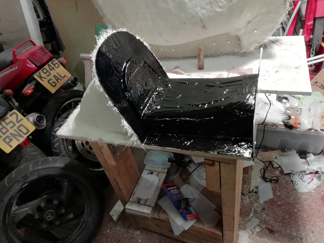
Whilst waiting for the various coats of resin on the tank mould to cure I turned my attention to the seat pattern and in particular the mould divider. I originally intended to split the mould longitudinally along the centre-line but decided that it would be a lot easier to do it laterally just aft of the start of the seat hump. This has the added advantage that the inevitable flash line will be hidden beneath the seat upholstery.
I was about to start fixing the divider to the pattern when it dawned on me that when extending the length of the seat pattern and providing a more sculptured base I had completely forgotten about the interface between the tank and the seat base (originally a simple butte joint). I had become obsessed with making the seat base look less like a plank and had spent a lot of effort raising the front and providing curved profiles towards the front of the seat base. The result was that the leading edge had grown 25mm to 30mm in height and width. If I had moulded it from that modified pattern it would have looked like additional air scoops immediately aft of the tank.
The heavy duty blacksmith’s rasp was pressed into service to reduce the width of the carefully sculpted and laboriously rubbed down front profile of the seat by about 25mm. The seat base now looks like a plank again, a curved plank but still a plank, this took about 2 hours and was a bit heart breaking.

Due to a basic original design flaw (not considering the thickness of foam and upholstery at the front of the seat when making the seat base) whatever happens there will be a slight aesthetic disconnect at the junction between the tank and the seat. The tank has near vertical sides with the rear outer edges tangential to the outer width of the frame rails with virtually no overhang beyond the frame rail width. The sides of the seat base have to/currently sit outside the frame rails and the width of the seat moulding has to allow for the thickness of:
a) the CF of the seat base itself,
b) any foam on the outside of seat base at the front,
c) the ambla seat upholstery on the outside and
d) the ambla on the inside of the seat base and any mechanical fixing to the seat base (contact adhesive or the hook and loop parts of Velcro tape?).
This is an absolute minimum of 6mm step each side assuming no foam whatsoever at the front on the sides. I originally intended to have 6mm closed cell rubber foam on either side of the seat flanks, I could try to taper this towards the leading edge but think that any abrasive applied to this type of foam will cause it to grip and tear. Plastic foam might work but is nowhere near as good, some experimentation is required.
350TSS is offline   Reply With Quote
Old 12-03-2019, 06:27 PM   #14
350TSS
Too much time on my hands member
 
350TSS's Avatar
 
Join Date: Jan 2013
Location: Shipbourne
Bike: M900
Posts: 1,419
On the tank top the two large halves are now bolted together and the ignition switch cut-out is now gel coated.
The seat mould divider has now been attached (hot glue gunned) and the first mould gel coat applied to one half of the mould.
chase branch bank near me
There are two consequences of lengthening the seat by 50mm, the first is that this:


which I made very early in the project from 3mm aluminium will no longer fit as the mounting pick up points onto the residual tea tray frame tubes are now 50mm adrift, the second is that my number plate has a distinctly better chance of avoiding a collision with the rear wheel on full bump.
I will re-design the component to make it in CF but it will definitely not be an easy pattern/ mould to make. I suspect that given that I do not yet know the exact location of the seat it would make sense to manufacture it in 2 parts; a) the rear light/camera holder to be attached to the seat hump and b) the number plate holder /rear seat hump support structure attached to the frame. I am sure I can save at least 150g by going to CF from aluminium if I get the design right. Readers will be pleased to note that I am almost certain there are now no further possible CF components that I can make for the bike.
I also spent some time today cutting cotton patterns, (subsequently transferred to cardboard) for the other CF moulds.
Whilst looking for something else I got distracted and found the oil pump which I then stripped, it was spotless inside with just some witness marks (probably less than 0.001”) where the gears run against the retaining plate. I lapped these out on a surface plate with some 240/600 wet and dry and after thoroughly cleaning everything with paraffin I torqued the 6 x 6mm socket cap screws back up again (9Nm) and sealed it in a plastic bag.
350TSS is offline   Reply With Quote
Old 16-03-2019, 06:19 AM   #15
350TSS
Too much time on my hands member
 
350TSS's Avatar
 
Join Date: Jan 2013
Location: Shipbourne
Bike: M900
Posts: 1,419
I finished the tank top mould yesterday and once it was cured had to separate it from the stand it was on.
Up until the tank mould I have been using Easy Composites for all the CF and GF resin and matting supplies. It is good stuff but EC are at the top end of the market for price. Their polyester resin is sea water green and translucent and quite viscous, think EP90. I shopped around for polyester resin and bought some cheaper stuff which is cream coloured and much less viscous, think 10W fork oil. Aside from the price benefit it is much easier to wet the glass mat and seems better at resisting the formation of air pockets when stippling the resin. The downside is that it runs everywhere and on the tank mould with near vertical sides resin puddles formed naturally at the bottom of the tank sides at the junction with the base board. It took about 2 hours with a wood chisel to separate the mould from the base.
From a cursory inspection (and without separating the three parts of the top mould) it looks as though the tank top mould has come out well with the flanges nice and flat and well defined. I also think that the tank bottom mould can be done as one piece.
Picture below shows mould just as I turned it over with all the debris from releasing it still in it
exxon station near me
What has become evident though is that my original planned scheme to bond the tank top to the bottom will not work. If I had thought about it for more than a nano-second then it was blindingly obvious that it would never have worked as when the two halves are introduced to each other there will be a very fine single point of contact between them which will not bode well for either strength or juice retention capability.
It is clear that I will have to form a “ledge” about 10 to 20mm wide on the inside of the tank top marrying accurately with the profile of the tank bottom about 5mm above the bottom edge of the tank. When the tank bottom is formed it will have to be cut about 0.5mm undersize so that it fits inside the tank top and sits comfortably and consistently on this ledge. This is not going to be easy and as I sit now I have no real clue as to how to do it. The underside of the tank at the junction with the tank top along both flanks is semi-circular to accommodate fitting over the frame rails, it is only at the front and back that a right angled “ledge” is possible.
The other possibility is to mould the tank bottom and form an “up stand” all around the base mould that marries with the profile of the inside of tank top.
On balance the “ledge” appears a better solution as it will be easier to ensure that contact between the two halves is complete and that resin contact between them is continuous but forming it accurately along the edge of the underside of the tank top will be a significant challenge.
The hump part of the seat mould is now complete and a first gel coat has been applied to the seat part.

Work continues with cutting cotton patterns for the CF to go into the moulds
350TSS is offline   Reply With Quote
Reply


Posting Rules
You may not post new threads
You may not post replies
You may not post attachments
You may not edit your posts

BB code is On
Smilies are On
[IMG] code is On
HTML code is Off

Forum Jump


All times are GMT. The time now is 06:27 AM.

vBulletin Skins by vBmode.com. Powered by vBulletin® Version 3.8.3
Copyright ©2000 - 2024, Jelsoft Enterprises Ltd.