UK Monster Owners Club Forum » .: Technical :. » Mods & How To's » Slow Monster rebuild

Reply
 
Thread Tools Display Modes
Old 14-03-2020, 01:20 PM   #1
350TSS
Too much time on my hands member
 
350TSS's Avatar
 
Join Date: Jan 2013
Location: Shipbourne
Bike: M900
Posts: 1,421
I need to make up a set of oil cooler hoses. Early 900SS low level hoses would fit (without the additional pipes for the carb heater hoses) but Ducati want a lorra lorra money for them.
Does anyone know the thread sizes (or type designations) for the connections to the crankcases and the cooler itself? I cannot clearly identify the thread with my thread gauges.
I assume they are metric. Most of the fittings advertised on e bay are 1/2" BSP
Thanks
350TSS is offline   Reply With Quote
Old 14-03-2020, 02:19 PM   #2
Albie
Fanactical volunteer
 
Albie's Avatar
 
Join Date: Oct 2003
Location: Kent
Bike: M900
Posts: 9,033
A fair few on ebay. Most come with cooler too but that could be sold off. USA has them but postage is the issue.

https://www.ebay.co.uk/itm/174148757459
Albie is offline   Reply With Quote
Old 14-03-2020, 02:25 PM   #3
Mr Gazza
Lord of the Rings
 
Mr Gazza's Avatar
 
Join Date: May 2013
Location: Norwich
Bike: M900sie
Posts: 5,859
M14 x 1.5

Interesting thread here but photos have gone unfortunately. http://www.ukmonster.co.uk/monster/s...ht=timing+side
__________________
Mr Gazza is offline   Reply With Quote
Old 15-03-2020, 10:05 AM   #4
350TSS
Too much time on my hands member
 
350TSS's Avatar
 
Join Date: Jan 2013
Location: Shipbourne
Bike: M900
Posts: 1,421
Thanks Mr Gazza - that is my next hour or so sorted, trawling the internet - also shame about the pictures in the other thread
350TSS is offline   Reply With Quote
Old 15-03-2020, 11:05 AM   #5
350TSS
Too much time on my hands member
 
350TSS's Avatar
 
Join Date: Jan 2013
Location: Shipbourne
Bike: M900
Posts: 1,421
All parts bought - £40.57 - I went for 2 x 90 degree elbows and 8 x straight swivel seal AN6 connectors to get the hose from the crankcase to the LH side oil cooler connection as that way I can be sure I do not foul the exhaust pipe, more joints and more weight but safer in the long run I think.
350TSS is offline   Reply With Quote
Old 17-03-2020, 06:12 PM   #6
350TSS
Too much time on my hands member
 
350TSS's Avatar
 
Join Date: Jan 2013
Location: Shipbourne
Bike: M900
Posts: 1,421
Not much progress the last few days as had to pick up No 1 and No 2 offspring prematurely from university, one from Birmingham and one from Oxford, unfortunately on separate days - total 13 hours on the most boring roads in Britain.
Sprayed the hugger mat black but it had loads of annoying little pin holes in the surface, so I filled it and either the filler, which is reaching the bottom of a 5 litre tin is going off or, more likely, I was a bit too Scrooge with the hardener so it took about 3 days to be hard enough to rub down.
It is however now done and looks OK, though I wish the design itself was not so obtrusive (think Hardly Dangerous Electraglide fenders as they call them).
Today was spent knocking up a support for the wiring entering the MU unit.
An added bonus of fixing the CoG of the wiring harness at the back of the tank is that I can shorten the limbs of the loom, most of which go to the MU unit, by simply shortening the wires as they enter it (without disturbing the AMP connectors at the other end).
My ETTC is now down to 89 hours of which 36 is wiring, 24 assembly and 29 is painting the tank, seat and fly-screen.
350TSS is offline   Reply With Quote
Old 21-03-2020, 04:08 PM   #7
350TSS
Too much time on my hands member
 
350TSS's Avatar
 
Join Date: Jan 2013
Location: Shipbourne
Bike: M900
Posts: 1,421
Well the cable support certainly proved challenging, a right PITA in fact.
In order to get on with shortening the limbs of the loom I need the MU unit to be positively fixed and the cables to it to be held firmly in place. The MU unit relies on small grub screws clamping on crimped aluminium tails pushed into the unit. It is not satisfactory from an installation standpoint (one connection has already parted with all the manipulation the wiring has had over the last week whilst I decide where each wire will be routed) and, once running, I think the vibration etc will reek havoc with those connections when I eventually get to ride it.
I wanted something light and simple that held the cables in place and would be vibration resistant. The complication were the space envelope it had to occupy and it had to be something I was physically capable of making.
After the best part of 10 hours here it is:

the base is made from 1 mm aluminium with 2 lengths of 12 mm x 12 mm x 1 mm aluminium angle pop riveted on either side. It had to be 12 mm to move the MU unit away from the head stock tubes and allow a reasonably straight entry for the cables into the locating grub screws. 12 mm was however too deep so the Mu unit had to be spaced off the base plate, accordingly 2 x 6mm thick bosses were aluminium soldered to the base plate.
Not shown but on each side some closed cell draft excluding foam will be glued to the angle attached to the base plate and to the inside of the two clamps (also made of 12 x 12 x 1 mm aluminium angle with one side cut back to 3mm).
4 x 4 mm aluminium rivnuts were attached to the base plate angle and 4 x 4 mm SS button head socket screws will clamp the cables up into the foam,
It took a long time and I think it will work.
Here it is in position under the ignition switch.


I retired too cold to continue today but the wiring can continue next week, but for one thing, my son's car failed MOT and now he is back from university he wants to out driving it so I have 10 days to weld up the rear trailing arm hanger bracket or pay the MOT fee again. I think quite a lot of fabrication work is required plus more than a few hours lying on the cold floor. I really hate working on cars.
350TSS is offline   Reply With Quote
Old 23-03-2020, 05:32 PM   #8
350TSS
Too much time on my hands member
 
350TSS's Avatar
 
Join Date: Jan 2013
Location: Shipbourne
Bike: M900
Posts: 1,421
Yesterday and this morning was fixing little perforations on my sons Honda Jazz. plastic inner wing had to come out before I could see what needed to be done and that meant removing the NS rear shock
When the MOT tester gave me the news I was struggling to see the issue but with the inner wing off the hole next to the 19 mm bolt should not be there.

Here it is after half an hour with a flappy wheel on a 110mm angle grinder

I cut some 1.5mm plate and shaped it to fit and to reinforce the bolt hole, that took about an hour.
the holes around the top are so I can first plug weld it before seam welding all around the edge
websites for upload images
And welded in with filler over my bird **** welding to stop any moisture getting between the steel laminations and primed. Lashings of black underseal tomorrow and job should satisfy MOT man.
explain the difference between short term and long term goals.
350TSS is offline   Reply With Quote
Old 23-03-2020, 05:56 PM   #9
350TSS
Too much time on my hands member
 
350TSS's Avatar
 
Join Date: Jan 2013
Location: Shipbourne
Bike: M900
Posts: 1,421
Next I made up a block to sit under my bike lift which has a positive stop leaving the table 28 inches above ground, This is too high for working on the wiring around the head stock and I do not trust the ancient hydraulic ram to stay at a more reasonable 14 inches without the load being taken off the ram seals. 2 x 9" x 3" baulks of timber cut 14" long worked admirably.
Finally about 2 o'clock I got down to some proper Monster work. I was about to bolt the rear hugger into position when I noticed that the filling I did a couple of days ago was showing through the mat black, not literally, but it was clear from the surface of the paint where it had been put. Clearly the paint continues to shrink as the solvent comes out of it.
It was rubbed down again and another couple of coats of mat black laid down. This is what it looks like now but I have a feeling I might be doing it again in a couple of days.

I did manager to shorten a couple of leads, battery to solenoid, battery through main fuse RCD to MU unit but I think I need to get the battery bought so I can wire exact lengths rather than guessing where the terminals will sit. There is a lot of mileage left yet in this wiring malarkey.
To keep my spirits up, a couple of state of play pictures.

350TSS is offline   Reply With Quote
Old 29-03-2020, 06:34 PM   #10
350TSS
Too much time on my hands member
 
350TSS's Avatar
 
Join Date: Jan 2013
Location: Shipbourne
Bike: M900
Posts: 1,421
I have not had much time on the Monster wiring these last few days as I had to fix a couple of other issues on my son's Jazz. The previous owner had fitted some aftermarket door mirrors but without side repeater indicators, and the MOT tester failed it not just for the rust but the lack of side repeaters.
What a can of worms. In fitting the door mirrors there is a harness in each door that goes to the mirrors with a 9-way block connector, for bits that are not fitted to this particular model (electric mirror adjustment, mirror heaters etc etc.). The moron had simply chopped the wires exiting the 9-way block connectors with about 6 mm spare and left them all bare ended. Nearly sorted now (awaiting the supplier of new mirrors to send me two that were LH and RH handed and for the same make of car - Doh!!) so I could get on with the bike today.
I have abandoned the wiring support arrangement into the MU unit, it was just too difficult to get the dimensions to work in the constrained space, it was too wide to fit tight to the headstock and if I spaced the MU unit away from the headstock it fouled the ignition switch and, if I then lowered it, encroaching on the space for the Ignitech unit became the issue. I must have spent about 12 hours making it and trying to fit it.
I had another less than 100% outcome in making up the oil cooler pipes. I originally intended to use 2 x 90-degree elbows to carry the oil cooler pipe behind the exhaust pipe, but when I looked at it with the unions in my hand I realised that the use of 2 unions before the elbow (one to the engine and one to the elbow) would have meant that the pipe between the two unions would have to be about 10mm long else the pipe would foul the exhaust.
I am using SS braided 8 mm bore pipe and it is a right bugger to work to get the union to screw onto it without a) fraying the SS braiding and b) tearing the ends of your fingers to shreds on the wickedly sharp cut ends of the braid. In the end, I wrapped the end in masking tape and cut it through the tape with a 1 mm cutting disc in the angle grinder.
When I made up the hose to the LH side of the cooler it had to go through 2 x 90 degree bends and the hose looks as though it has distorted, not quite to the extent of cutting off the flow but certainly there is the possibility of a restriction. It might just be the pipe twisting as I do up the unions
I spent this afternoon routing the wiring from the seat to the headstock and doing it a second then a third time until I was satisfied that I had the best, most hidden route clear of the rear suspension rocker, shock absorber, belt covers, petrol pipes, choke cable etc.
The big trouble with everybody else being home is that the home job list seems to grow?????

Last edited by 350TSS; 29-03-2020 at 07:25 PM.. Reason: correction
350TSS is offline   Reply With Quote
Old 06-04-2020, 06:26 PM   #11
350TSS
Too much time on my hands member
 
350TSS's Avatar
 
Join Date: Jan 2013
Location: Shipbourne
Bike: M900
Posts: 1,421
This last 10 days I have mostly been "faffing". Starting on something then getting distracted with something else and at the end of 3 hours, I had made bugger all progress on anything.
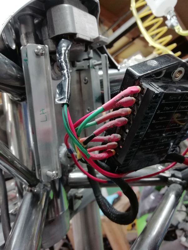
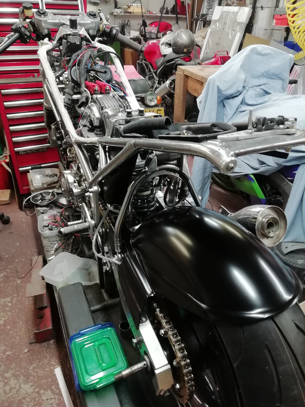
The trouble is that all the wiring is so congested around the headstock that touching or trying to sort one wire/one circuit out means that everything gets disturbed and the circuit you have just sorted is now wrong and needs re-routing. Its fiddly work and laborious and not at all satisfying.
Some progress has been made though, I have decided to discard my design for controlling the wires around the headstock as there just is not the room for it. No alternative solution for a great big bundle of wires, separately loomed suffering turning forces around the headstock is currently obvious.
I did manage to make an adapter to take the M900 brake light switch onto an S4 master cylinder.
I have 5 circuits to complete before I test it all
1. Hall effect ignition triggers to Ignitech unit
2. Ignitech unit to coils
3. Rectifier to dashboard charging light
4. MU unit to starter solenoid
5. Voltmeter to a switched power circuit
6. Power to camera and monitor switched circuit


If I had my time again I would a) definitely not have wired off the bike on a jig, b) probably not have used AMP connectors as they are quite bulky and quite long so require about 100 mm long straight runs and c) not put as many connectors into the loom and just wired component to component.

For the last 3 days, I have felt really, really tired to the point I slept 16 + hours a day consecutively, no other symptoms whatsoever. I do not want to go to the doctor as I am in a higher risk category as I should be on immune suppressants for rheumatoid arthritis although I had to stop them 2 weeks ago as I was on antibiotics for skin boils, a relatively frequent and bad side effect of the immune suppressants. Hopefully, I have now had the Covid thingy, maybe, maybe not.

Feeling better today I had strict instructions from SWMBO to get my 14 year old off electronic devices, a pleasant day was therefore passed instructing said boy on removing main bearings from a MZ TS125
nearest petrol station
350TSS is offline   Reply With Quote
Old 13-04-2020, 07:06 PM   #12
350TSS
Too much time on my hands member
 
350TSS's Avatar
 
Join Date: Jan 2013
Location: Shipbourne
Bike: M900
Posts: 1,421
This last week I have still been feeling a bit odd and sleeping about 14 hours a day and when I did get into the garage I have been skirting around getting really stuck into the wiring. There were 2 reasons for this, the first was that I had to think of a way of getting the loom around the headstock and could not work out a design I was happy with and the second was that I am fairly sure I will have to cut off the AMP connectors and fit more conventional bullet connectors because of space considerations. My reluctance had quite a bit to do with the length of time it took to put them on in the first place.
Some may find my determination to find a solution to getting around the headstock with the loom a bit obsessional, but I have owned four bikes where I suffered from intermittent wiring issues (XBR Honda, Honda Bros, KZ400 and ZX9R Kwaks) and it is a right PITA when it strikes.
Below is a picture of the Mk 2 and Mk 3 versions of my solution.
The Mk2 on the right, now discarded, relied on a carrier for the AMP connectors which swivelled when the steering was turned.
The Mk 3 is bolted to the underside of the top yoke through the RH handlebar clamp threaded holes and consists of a 6 mm aluminium plate through which 2 x 6 mm csk socket screws are attached to two 20 mm diameter bushes through drilled and tapped 6 mm.
2 x 8 mm titanium spindles are turned down at each end to 6 mm and threaded at each end with a plain space for 4 x 17 mm x 6 mm x 6 mm sealed ball races. The rollers are 19 mm plastic electrical conduit bored at each end to accept the ball races.
A 6 mm aluminium plate at the bottom holds the rollers in line.
The wiring loom(s) will pass between the rollers which will turn with the steering.

Last edited by 350TSS; 14-04-2020 at 02:08 AM.. Reason: correction
350TSS is offline   Reply With Quote
Old 14-04-2020, 12:04 AM   #13
manwithredbike
aka Phil
 
manwithredbike's Avatar
 
Join Date: Nov 2005
Location: derry
Bike: M900
Posts: 376
A very elaborate setup there and looks really well made. Have you considered using extra length and simply putting a helix or loop into the loom at the headstock area to 'absorb' the movement?
__________________
..
~
manwithredbike is offline   Reply With Quote
Old 14-04-2020, 02:17 AM   #14
350TSS
Too much time on my hands member
 
350TSS's Avatar
 
Join Date: Jan 2013
Location: Shipbourne
Bike: M900
Posts: 1,421
Manwithredbike: Yes I have considered a loop/spiral but this has two problems;
1. space for it and where it would sit - ideally it would have to be centred on the tangent between the frame exit point for the loom and the headstock so at about 2.00 0'clock in plan view above the headstock. I have 20 + wires 1mm OD going around that corner, instrument nacelle, speedo sensor, LH and RH switchgear and front brake light switch, CCTV screen, headlamp and front indicators.
2. when I made the loom up I bought thin wall insulation cabling which actually seems to have stiffer composition insulation, added to the fact that in selecting the wire core size to use for each circuit I have chosen conservatively, probably using larger copper content than was strictly necessary for that particular circuit. Some might argue it is a problem of my own making.
350TSS is offline   Reply With Quote
Old 20-04-2020, 07:19 PM   #15
350TSS
Too much time on my hands member
 
350TSS's Avatar
 
Join Date: Jan 2013
Location: Shipbourne
Bike: M900
Posts: 1,421
After a week of sleeping a lot, I finally managed to get into the garage today and made some progress.
I fitted my rollers and some rubber edging to the infill panel on the frame and after a bit of fiddling and trimming got the battery tray to sit right with the frame and the wiring.
4 lengths of bicycle inner tube protect the looms as they pass through the infill panel and around the rollers and I managed to hang the excess loom from 2 large rubber "O" rings suspended from nylon "P" clips attached to the instrument mounting studs.
I had to lose my re-settable 25 amp main fuse as there just was not enough room for it, I am now waiting for a waterproof 25 amp fuse holder to go between the battery and the positive side of the MU unit.
I managed to confirm that my starter solenoid fires (clicks) OK and confirm that it does not matter which orientation the input leads are connected, just as well as I forgot to make a note of the wiring and colours to it.


350TSS is offline   Reply With Quote
Reply


Posting Rules
You may not post new threads
You may not post replies
You may not post attachments
You may not edit your posts

BB code is On
Smilies are On
[IMG] code is On
HTML code is Off

Forum Jump


All times are GMT. The time now is 01:50 AM.

vBulletin Skins by vBmode.com. Powered by vBulletin® Version 3.8.3
Copyright ©2000 - 2024, Jelsoft Enterprises Ltd.