UK Monster Owners Club Forum » .: Technical :. » Electrics » Tell me more about S4RS indicators

Reply
 
Thread Tools Display Modes
Old 27-03-2010, 02:38 PM   #16
jezzamondo
Guest
 
Posts: n/a
That is comprehensive! Beautiful work Capo & thanks for the detailed posting! To date, I've just tried 15R in parallel with each indicator which gives the correct flash rate, about 12W an indicator. Then I put the same loads just on the rear in parallel (2x15R=7.5R, 25W right?) & I was back to rapid flash mode! It would seem the S4RS ('06) needs a load on each indicator...
  Reply With Quote
Old 28-03-2010, 12:29 AM   #17
jezzamondo
Guest
 
Posts: n/a
Thanks Capo, awesome post! You deserve multiple virtual beers for that, even real ones if I get the chance! I got the right flash rate in the end with 15R 7W on each indicator, then tried stacking them just on the rear (in parallel, 2 x 15R= 7.5R, right?)- no joy, my bike wants a load on each & every indicator. Just starting to wonder if cairojay hit on something & maybe the S4RS can be "convinced" LEDs are OK. Hope someone out there knows because I really don't think i can match Capo's attention to detail for mounting load resistors...
  Reply With Quote
Old 28-03-2010, 07:56 AM   #18
Capo
You Are What You Is
 
Join Date: May 2005
Location: A Foward Location
Bike: S4r
Posts: 1,948
Thanks,

BTW I got the front mounting arrangement idea from Stafford credit where it is due.

With regard to resistors in parallel, The total resistance is calculated by adding the reciprocal ( 1/Rn ) value of the individual resistances instead of the resistances themselves (as is the case with resistors connected in series). The formular looks like this (1/R1 + 1/R2 + 1.Rn = G) the resultant is a value known as Conductance, symbol G with the units of conductance being the Siemens, symbol S. Conductance is therefore the reciprocal or the inverse of resistance, ( G = 1/R ). To convert this conductance sum back into a resistance value we need to take the reciprocal of the conductance giving us then the total resistance, RT of the resistors in parallel.
One important point to remember about resistors in parallel, is that the total circuit resistance (RT) of any two resistors connected together in parallel will always be LESS than the value of the smallest resistor

The circuitry on the Instrument PCB incorporates a comparator circuit that looks at the load on the indicator, if the load is lower as would be the case with LEDS, then it thinks a bulb has blown and increases the flash rate. This is a design factor and I believe is a requirement by law.

Now interestingly, later models have the ability via 'programming' to select either incandescent or LED loads, it probably does this by switching to a second comparator circuit.

If I could get my hands on a spare board, I want to investigate this further so I can get rid of the resistors.

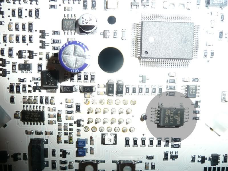
Here is a picture of the PCB with the indicator 'relay' identified under the shaded circle.


Last edited by Capo; 28-03-2010 at 09:04 AM..
Capo is offline   Reply With Quote
Old 28-03-2010, 12:35 PM   #19
jezzamondo
Guest
 
Posts: n/a
Excuse the double posting - thought first hadn't gone up, I'm not quite as excitable as all that... Thanks for the image - is that your S4R? So the load I put on the rear still should have been enough to convince the board all bulbs were present but didn't & Cairojay is reporting his indies are flashing at the right rate (although it might be interesting to know what that rate is if you are still following this cairojay) so I have a cleverer system - maybe a dip switch on the board? Perhaps there's a link that can be removed/put in? Can't see anything in the manual or online about it. Anyone?
  Reply With Quote
Old 28-03-2010, 03:33 PM   #20
Capo
You Are What You Is
 
Join Date: May 2005
Location: A Foward Location
Bike: S4r
Posts: 1,948
Therein lies the rub, there is no technical information available on this PCB, a sample that could be examined in detail would provide the information to alter the comparator circuit.
Capo is offline   Reply With Quote
Old 28-03-2010, 10:52 PM   #21
jezzamondo
Guest
 
Posts: n/a
pics of LED tail light & indicators

Some pics of the LEDs in action. I've not got the skill with a camera to capture the colour which is really iridescent, particularly the red globe through the red housing. The "white' of the number plate bulb replacement is that sharp icy white which looks cool too. All lights are unmissable now, result!

links for components if anyone is interested:

high intensity bulb

Thing I used for indicator

Have written to Ducati Capo to see if they can enlighten us on the dash circuitry, I can't see myself stumbling on another dash anytime soon & I've got an MOT to get thru!
Attached Images
File Type: jpg IMG_0647.jpg (30.3 KB, 17 views)
File Type: jpg IMG_0648.jpg (28.5 KB, 14 views)
File Type: jpg IMG_0651.jpg (30.2 KB, 13 views)
File Type: jpg IMG_0653.jpg (29.7 KB, 14 views)
  Reply With Quote
Reply

Tags
led, rela, s4rs


Posting Rules
You may not post new threads
You may not post replies
You may not post attachments
You may not edit your posts

BB code is On
Smilies are On
[IMG] code is On
HTML code is Off

Forum Jump


All times are GMT. The time now is 04:30 AM.

vBulletin Skins by vBmode.com. Powered by vBulletin® Version 3.8.3
Copyright ©2000 - 2024, Jelsoft Enterprises Ltd.