Register | FAQ | Members List | Calendar | Today's Posts | Search | Contact |
|
Registered
Members: 673 | Total Threads: 50,934 | Total Posts: 519,365 Currently Active Users: 801 (0 active members) Please welcome our newest member, Mozzer46 |
|
|
Thread Tools | Display Modes |
|
10-08-2020, 02:30 PM | #1 |
Registered User
Join Date: Aug 2011
Location: Southampton
Bike: M1100evo
Posts: 2,465
|
A simple series of tests for your rectifier
Ok, so this isn't a Ducati component, (it's actually from my Gilera), but the tests can be used on most rectifier units, including Monsters. Since Regulator/Rectifier (R/R) problems seem to appear quite frequently on the forum, I thought I'd share these tests as someone else might find them useful.
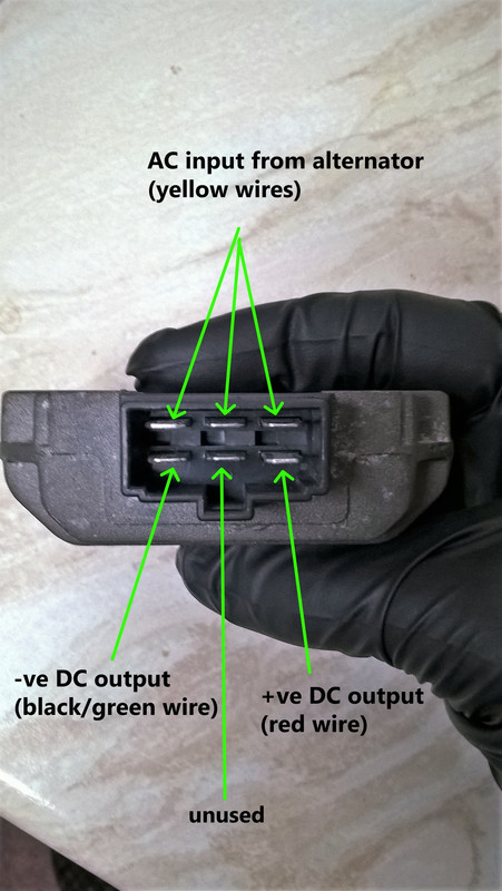
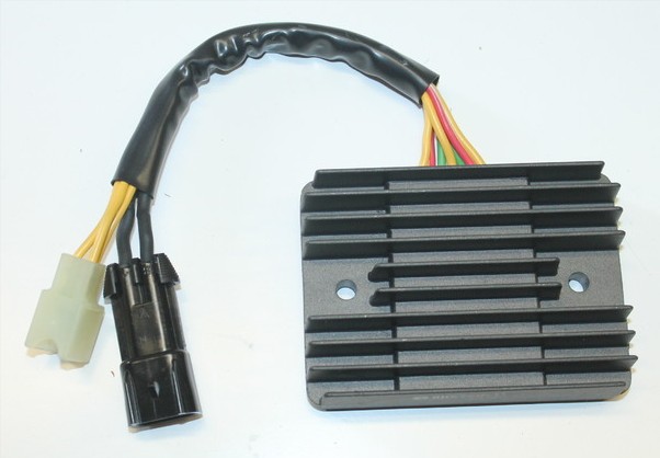
For identification purposes, this is a three-phase, full-wave, bridge rectifier using six diodes to convert the AC voltage from the alternator to DC voltage to the battery. Simplified rectifier diagram Gilera 5-wire rectifier All of the current Monsters should similarly be three-phase (with three yellow wires), but the early versions had single-phase alternators (two yellow wires) and so will have a different R/R to suit. The Monster R/Rs also have dual positive (red) and negative (black or green) wires, (making seven in total), which are sometimes siamesed together as here. Typical Monster 7-wire rectifier My problem I'd noticed that my battery was going flat despite being boosted by an Optimate. Preliminary checks The first suspect was the battery itself. Although it's only a couple of years old, it doesn't get used much so could have deteriorated. However, after fully charging it, it held 12.8V for a week, so then the alternator seemed a likely culprit. Checking the voltage at the battery with the engine at 3,000 revs gave only a maximum of 12.5V when you'd expect high 13/low 14V, which again suggested the alternator. An (external) check of the alternator with a multimeter suggested that it was working normally, so that just left the R/R, (all connecting wiring appeared fine). I'd not really considered the R/R as usually, when it fails, it seems to result in overcharging rather than undercharging. To check the rectifier component of the R/R, there are four tests to be made on each of the three alternator connections (12 in total). So first turn your meter to the diode check facility: Last edited by Luddite; 10-08-2020 at 02:44 PM.. |
10-08-2020, 02:32 PM | #2 |
Registered User
Join Date: Aug 2011
Location: Southampton
Bike: M1100evo
Posts: 2,465
|
Test 1: Forward Bias of Positive Circuit Diodes
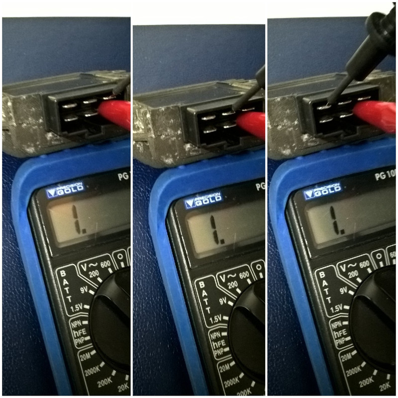
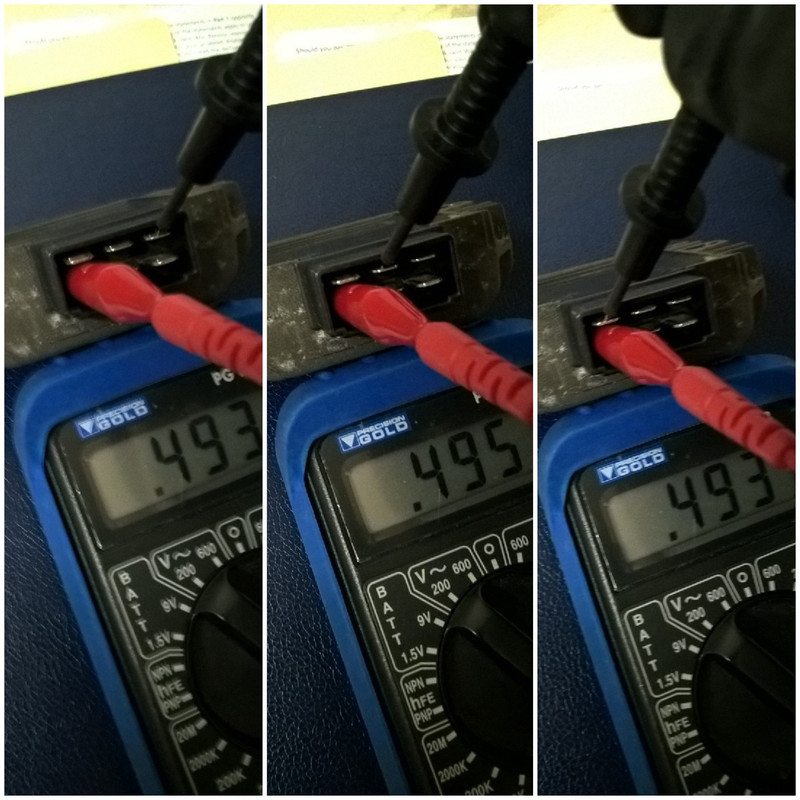
Put the meter's negative lead on the positive (red wire) terminal of the R/R. Then, put the meter's positive lead on all three terminals in turn of the alternator (yellow wire) connectors. The meter should show a forward voltage drop of around 0.5V, which indicates that each diode is allowing current to pass (forward bias), and is therefore working properly. All three results should be approximately the same. (Note the variance from the left hand connector, which could indicate a problem.) Test 1 results Test 2: Reverse Bias of Positive Circuit Diodes Put the meter's positive lead on the positive (red wire) terminal of the R/R. Then, put the meter's negative lead on all three terminals in turn of the alternator (yellow wire) connectors. The meter should give a reading of "1." (on my meter), or "OL", (which stands for open loop), on some other meters. This shows that the diode is preventing current from passing back through (reverse bias), and is therefore working properly. All three results should be the same. Test 2 results Test 3: Forward Bias of Negative Circuit Diodes Put the meter's positive lead on the negative (black or green wire) terminal of the R/R. Next, put the meter's negative lead on all three terminals in turn of the alternator (yellow wire) connectors. The meter should give a positive reading as in test 1, which indicates that each diode is allowing current to pass through. Again, all three results should be approximately the same. Test 3 results Test 4: Reverse Bias of Negative Circuit Diodes Put the meter's negative lead on the negative (black or green wire) terminal of the R/R. Next, put the meter's positive lead on all three terminals in turn of the alternator (yellow wire) connectors. As in test 2, the meter should give a reading of "1." or "OL", which indicates that each circuit is open, and the diode is working properly by preventing current from passing back through. If any of the forward bias test readings fail to show a voltage of around 0.5V*, or if any of the reverse bias test readings show a voltage, the diode has failed. (*For comparison,I tested the new R/R and all six forward bias readings were identical at 0.520V.) Test 4 results In my case, the reverse bias test on the left contact showed a voltage, rather than the correct open circuit, indicating that the diode was shorted and therefore faulty. A new R/R was fitted and, 'eccola!', back to a healthy 14.3V charging current. So, if your battery is not being fully charged, don't automatically blame the alternator - check your rectifier too. Last edited by Luddite; 10-08-2020 at 02:37 PM.. |
10-08-2020, 05:24 PM | #3 |
Too much time on my hands member
Join Date: Jan 2013
Location: Shipbourne
Bike: M900
Posts: 1,422
|
Brilliant explanation - please can we make this a "sticky" - Thanks
|
11-08-2020, 12:14 AM | #4 |
Old Git
Join Date: May 2006
Location: Cricklade
Bike: Multiple Monsters
Posts: 2,897
|
Thankyou 350SS what a wonderful tutorial
__________________
MONSTERMAN |
11-08-2020, 09:15 AM | #5 |
Registered User
Join Date: Oct 2019
Location: Chorley
Bike: M900
Posts: 160
|
Thank you. Very helpful . Thinking of other bikes, how do you tell if you have single phase or 3 phase, eg are most modern Jap /German/British bikes 3 phase ?
__________________
Contents may settle ! |
11-08-2020, 11:25 AM | #6 |
Registered User
Join Date: Apr 2016
Location: Farnborough
Bike: M900sie
Posts: 185
|
|
11-08-2020, 10:16 AM | #7 |
Member
Join Date: Sep 2011
Location: Telford
Bike: S4r
Posts: 175
|
This is awesome thanks
I was looking at getting one of these https://www.rmstator-europe.com/en/7...54040111c.html |
11-08-2020, 11:35 AM | #8 | |
Registered User
Join Date: Apr 2016
Location: Farnborough
Bike: M900sie
Posts: 185
|
Quote:
In fact, I just checked Flea Bay, and the same seller (james_sherlock) I bought the other two from was listing one removed from a Yamaha for 29 squid, free postage. Just bought that too, so now all my Monsters will get one... (A series R/R draws only the current from the alternator that the bike is consuming. A shunt runs the alternator 100% duty cycle 100% of the time - and shunts any excess it doesn't want back into the stator windings, making them hotter and the wires crispier). Adding in the most expensive Triumph link cable I bought (30 quid) still comes in cheaper than a shunt from an unknown manufacturer. Or you could have superior technology made by the Japanese OEM supplier to almost every motorcycle manufacturer on the planet. Your choice... Last edited by spuggy; 11-08-2020 at 11:45 AM.. |
|
11-08-2020, 06:43 PM | #9 |
Guest
Posts: n/a
|
Brilliant tutorial,more advice please !
Great tutorial Vince, once again I am doffing my cap at your knowledge. I would like some more advice if you can oblige. So I am.....well a Luddite () when it comes to electrics....sorry about that....so I went to start my new addition earlier(S2r 1000), and battery was low. Plugged in the optimate and we are showing 11.3 v ,89amp. I let it do its thing for an hour then hey presto we are back in the game.
With the engine running we are now showing 14 v( I think this indicates alternator is doing its bit ).......engine off and we are showing 12 v.an hour later 12.1v. So here are the questions, if it's a 12 v battery,with the engine off it will never be more than 12 v will it as that's the capacity of the battery???? If the answer to above is , correct it will max out at 12 v, then why is the optimate charge indicator still showing "low". Please give your answers at "thicko" level |
12-08-2020, 09:15 AM | #10 |
Registered User
Join Date: Aug 2011
Location: Southampton
Bike: M1100evo
Posts: 2,465
|
Hi Mike. Sounds like your battery needs replacing to me. Although, nominally, they are 12V, each of the six cells that make the battery are 2.1 - 2.2V so, fully charged, the battery should read 12.6 - 12.8V. Anything less than 12.4V and you'll probably have trouble starting, especially with a Ducati.
To check, disconnect the battery, fully charge it for 8 hours then measure the voltage after an hour (this allows the 'surface charge' to dissipate for an accurate reading). Let the battery stand for another 24 hours and see what the voltage is - if it shows 12.4V or lower you've got a problem. As you say yours is only showing 12.1V just an hour after charging, I think it's Motobatt time! As an example, the battery on my Gilera dropped to 12.3V when it failed to start. After I charged it up it read 12.8V and held that charge for a week while I waited for the new R/R to arrive. Hope that helps. PS I found this table online, which is quite useful. You can see that, although your battery has only dropped maybe half a volt, it's actually holding less than 50% of the charge of a healthy battery. Last edited by Luddite; 12-08-2020 at 09:48 AM.. Reason: Diagram added |
12-08-2020, 01:36 PM | #11 |
Guest
Posts: n/a
|
Hi Vince, thanks for the advice,I will follow your instructions to the letter and let you know.The seller said he had replaced their battery recently , I was worried it was slowly draining, faulty earth or similar, will let you know ,cheers.
Mike |
12-08-2020, 07:38 PM | #12 | |
Member
Join Date: Sep 2011
Location: Telford
Bike: S4r
Posts: 175
|
Quote:
|
|
12-08-2020, 09:41 PM | #13 | |
Registered User
Join Date: Dec 2014
Location: Aylsham
Bike: Multiple Monsters
Posts: 200
|
Quote:
Spuggy and Luddite, for two excellent threads that have given me the confidence to dabble in electrics.
__________________
NFN |
|
13-08-2020, 12:27 AM | #14 | |||
Registered User
Join Date: Apr 2016
Location: Farnborough
Bike: M900sie
Posts: 185
|
Quote:
Yeh, actually, Fowler's in Bristol had 10 in stock on Tuesday (9 now, sorry boys ) https://www.fowlersparts.co.uk/parts/view/T2500676 They were cheaper than anyone I saw on Flea Bay @ 20.57 GBP (VAT included), and will pop them in a plain brown envelope and mail them out for 3-4 quid; got mine today. That's a pint you owe me Quote:
Do the same for the Ducati connector block on your original rectifier, and then you can swap the Ducati locking connector block onto the Triumph link cable - just adjust the terminal tang so it's slighly proud if it got flat, push the terminal into the block until it clicks/locks. And then you'll have the locking function on the block on the Triumph cable as well. Might want to add a small zip tie; the lock doesn't quite hold the connector 100% of the way in... (to clarify this is mostly to make it more weathertight - the electrical connection is fine) Quote:
Hit the button, big pause while it winds up - fires up every time... And they discharge 1% per month if you don't use the bike, not 10% like lead acid. I'm, like, so over lead acid/AGM technology... Last edited by spuggy; 13-08-2020 at 02:17 AM.. |
|||
13-08-2020, 05:37 PM | #15 | |
Registered User
Join Date: Aug 2011
Location: Southampton
Bike: M1100evo
Posts: 2,465
|
Quote:
As you say, it's fitted as standard to, for example, the 821 and 1200 Monsters and, knowing Ducati as we do, you wouldn't expect the bean counters to authorise a top spec R/R when a cheaper option is available. I was under the impression it was an unremarkable SCR shunt type (I think the S in SH signifies SCR circuitry and the F in FH indicates (MOS)FET). Having corresponded with Shindengen in the past, I pinged them an email for clarification and, to their credit, they replied straightaway: Last edited by Luddite; 13-08-2020 at 07:56 PM.. Reason: Series type model nos. added |
|
|
|